Contents
1.1 Background
1.2 Purpose of the Manual
1.3 Organization and Structure of the EM&A
1.4 Structure of
the EM&A Manual
2 Cable
installation water quality monitoring
2.1 Sampling and Testing Methodology
2.2 Monitoring
Locations
2.3 Sampling
Procedures
2.4 Compliance /
Action Event Plan
2.5 Reporting
4.1 Objectives and Approach
4.2 Monitoring Locations
4.3 Monitoring Methodology
4.4 Reporting
5 Compliance
Audit Procedures of Mitigation Measures
5.1 Site
Inspections
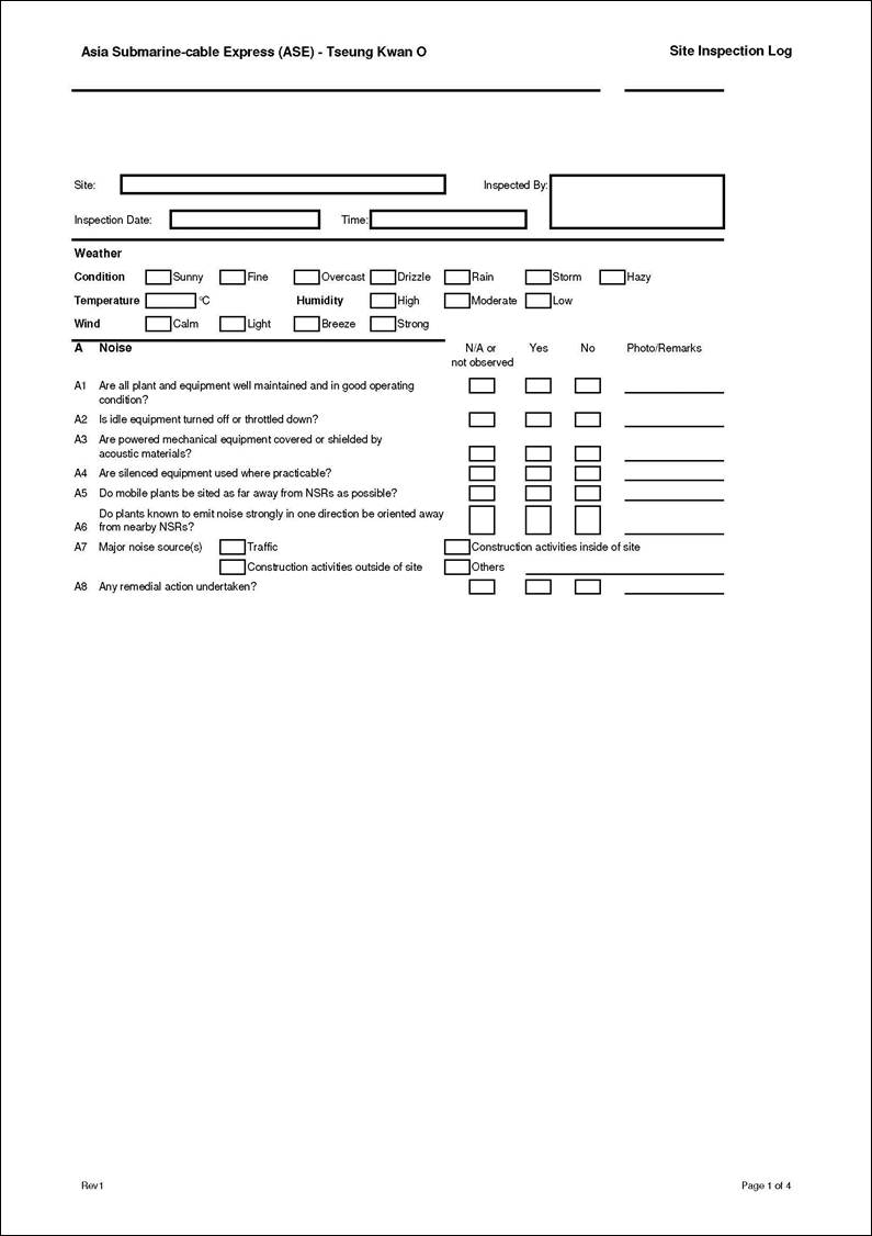
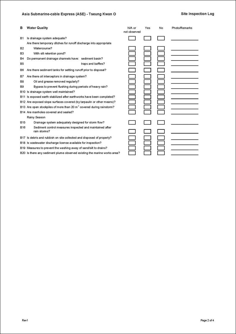
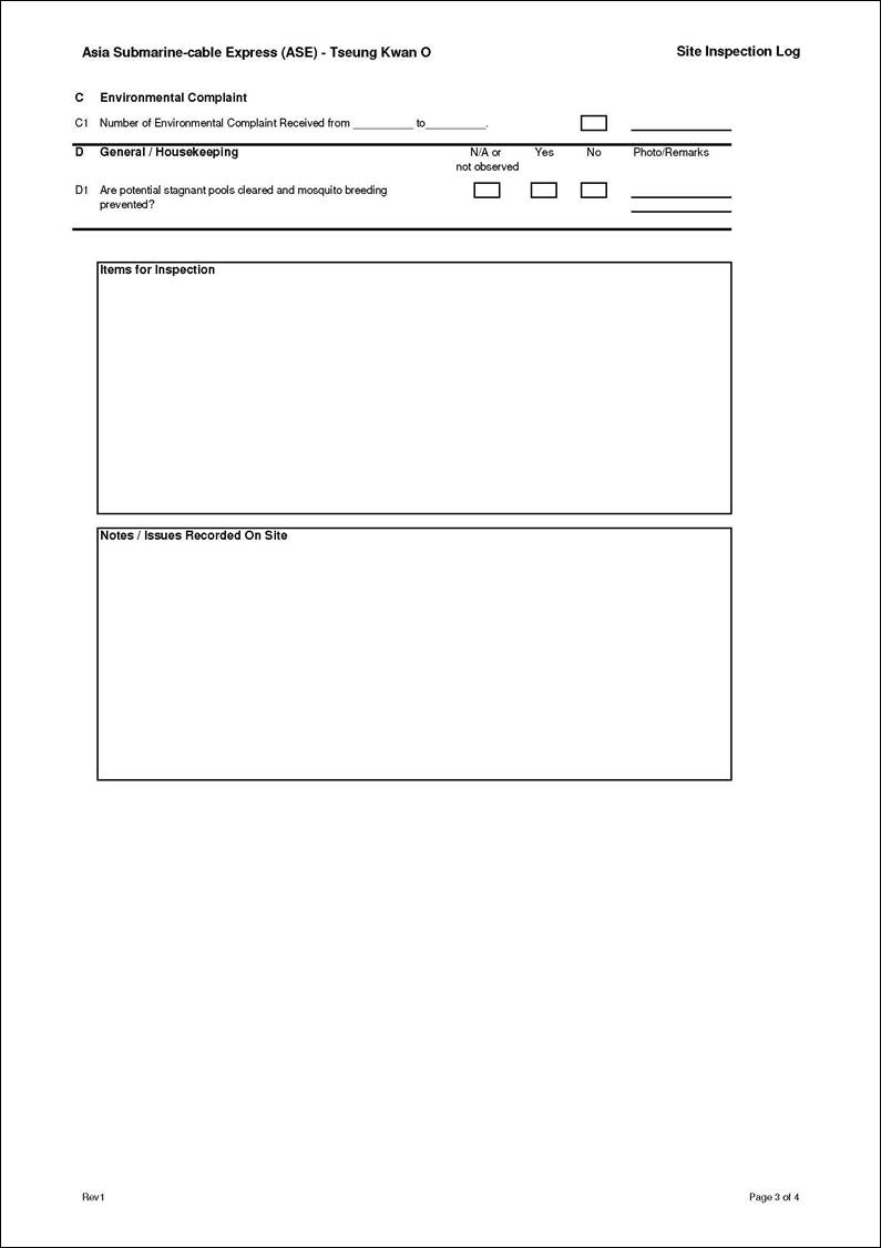
Annex A Site Inspection Log
Annex B Cable Re-Installation Procedure
1
Introduction
1.1
Background
NTT Com Asia
(NTTCA) proposed to install a telecommunication cable (Asia Submarine-cable Express
(ASE) cable) of approximately 7,200 km in length, connecting Japan and
Singapore with branches to the Philippines, Hong Kong SAR (HKSAR) and
Malaysia. NTTCA was responsible for
securing the approval to land the ASE cable in Tseung
Kwan O, Hong Kong SAR (HKSAR) and the proposed landing site is a new Beach
Manhole (BMH) which ultimately connects with a Data Centre in Tseung Kwan O (TKO) Industrial Estate which was completed
in 2012. It should be noted that Tseung Kwan O is currently the landing site for a number of
submarine cables. From Tseung Kwan O, the cable extends westward approaching the Tathong Channel.
Near to
The Project Profile (PP-452/2011) which includes an assessment of the
potential environmental impacts associated with the installation of the
submarine telecommunications cable system was prepared and submitted to the
Environmental Protection Department (EPD) under section 5.(1)(b)
and 5.(11) of the Environmental Impact Assessment Ordinance (EIAO) for the
application for Permission to apply directly for Environmental Permit
(EP). The Environmental Protection
Department, subsequently issued an approval letter on Application for
Permission to Apply Directly for Environmental Permit on 14th
November 2011 (Ref: (18) in EP2/G/C/161).
The assessment was based on information compiled by the Project
Proponent describing the expected Project
installation activities and an Environmental Permit (EP-433/2011) was granted on 20 December 2011.
The ASE cable was installed and first began operation
in early 2013 and post-Project monitoring was initially conducted revealing no
adverse effect due to the cable installation. Later in 2013 however, a section of the
sub-marine cable in HK waters was damaged in such a way that the cable totally
ceased to be operational for telecommunications traffic to/from Hong Kong. It is therefore necessary to re-install
any damaged cable to ensure the cable becomes fully functional once again.
The procedure for the re-installation is outlined in Annex A and the cable laying methodology
for re-installation works will follow the same methodology as for the initial
installation as described in the Project Profile (PP-452/2011) and follow all
conditions of EP-433/2011. The cable
re-installation is therefore considered to cause the same potential
environmental impacts as assessed in the Project Profile (PP-452/2011).
Once
operational the cable will not result in impacts to the environment.
During all
cable installation works it has been recommended that predicted environmental
impacts are monitored and checked as part of an Environmental Monitoring and
Audit (EM&A) programme. This EM&A programme
is relevant both to the initial installation works as
well as the re-installation works, according to the area of HK waters where
works will be conducted.
The key
aspects of the EM&A programme include Water
Quality, Marine Mammal (Finless Porpoise) and Coral Monitoring (conducted
according to the location of works) and are summarized as follows ([1]):
�P
The forward speed of cable laying barge will be
limited to a maximum of 1 km hr-1 so that the amount of seabed
sediment disturbed and dispersed during the cable laying process can be kept to
a minimum;
�P
Good house-keeping practices for onshore activities at
the cable landing will serve to avoid impacts to water quality;
�P
Silt curtain will be employed around the seawall area
to reduce the dispersion of sediments from the landing site;
�P
A water quality monitoring programme
will be conducted at Junk Bay, Tung Lung Chau, Tai Long Pai
to verify that adverse impacts do not occur to water quality, marine ecology
and fisheries due to the installation of the cable;
�P
A marine mammal exclusion zone within a radius of 250
m from the cable installation barge will be implemented during the cable
installation works to verify that the area is clear of marine mammals prior to
the commencement of works and to reduce any disturbance to them; and
�P
A coral monitoring programme
will be conducted at Cape Collinson and Tai Long Pai as well as the control site Tung Lung Chau prior to,
and after, the cable installation works to verify that no adverse impacts occur
to the corals that are in the vicinity of the cable alignment zone.
1.2
Purpose of the Manual
ERM-Hong Kong,
Limited (ERM) has been appointed by NTTCA to undertake the environmental
permitting and prepare the Environmental Monitoring and Audit (EM&A) Manual
(��the Manual��) for this Project.
This Manual is a supplementary document of the project entitled
The EM&A
Manual has been prepared to:
�P
Monitor the effectiveness of the control measures
employed during the cable installation (actual laying works as well as testing and finalisation works as
circumstances dictate) ;
�P
Verify that the project works are not resulting in any
impacts to water quality at seawater intakes at Junk��s Bay and Siu Sai Wan,
coral communities and Fish Culture Zone at Tung Lung Chau, and coral
communities at Tai Long Pai, Fat Tong Chau, Sung Kong
and Waglan Island;
�P
To ensure that any adverse impacts are detected during
the cable laying process and that appropriate action is undertaken in the event
that impacts are identified to sensitive receivers and are found to be
associated with the cable installation works;
�P
Verify the project works are not carried out if marine
mammals (ie Finless Porpoise) are within a radius of
250 m from the cable alignment site, so to ensure they will not be disturbed by
the cable laying works; and
�P
Carry out coral monitoring works at Impact stations
(Cape Collinson and Tai Long Pai)
which are in the vicinity of the alignment of cable and at Control station
(Tung Lung Chau) to ensure corals (ie hard corals, octocorals and black corals) are not affected by the cable
laying works.
1.3
Organization and Structure of the EM&A
1.3.1
General
NTT Com Asia
Limited (NTTCA) will appoint an Environmental Team (ET) to conduct the
monitoring and auditing works and to provide specialist advice on the
undertaking and implementation of environmental responsibilities. The ET shall have previous experience
with managing similarly sized EM&A programmes and
the Environmental Team Leader (ET Leader) shall be a recognized environmental
professional, preferably with a minimum of 7 years relevant experience in
impact assessment and impact monitoring programmes.
To maintain
strict control of the EM&A process, NTTCA shall appoint an independent
environmental consultant to act as an ��Independent Environmental Checker�� (IC(E)) to verify and validate the environmental performance
of the Contractor and his Environmental Team.
1.3.2
Project
Organisation
The roles and
responsibilities of the various parties involved in the EM&A process are
further expanded in the following sections. The ET Leader will be responsible for, and
in charge of, the Environmental Team; and shall be the person responsible for
executing the EM&A requirements.
Contractor
Reporting
to NTTCA, the Contractor shall:
�P
Work within the scope of the Project installation
contract and other tender conditions;
�P
Provide assistance to the ET in conducting the
required environmental monitoring;
�P
Participate in the site inspections undertaken by the
ET, as required, and undertake any corrective actions instructed by NTTCA;
�P
Implement measures to reduce impact where Action and
Limit levels are exceeded; and
�P
Take responsibility and strictly adhere to the
guidelines of the EM&A programme and
complementary protocols developed by their project staff.
NTTCA
NTTCA
will:
�P
Employ an ET to undertake monitoring, laboratory
analysis and reporting of the EM&A requirements outlined in this Manual;
�P
Employ an IC(E) to verify and validate the
environmental performance of the Contractor and his Environmental Team
�P
Monitor the Contractor��s compliance with contract
specifications, including the effective implementation and operation of
environmental mitigation measures and other aspects of the EM&A programme;
�P
Comply with the agreed Event and Action Plan in the
event of any exceedance; and
�P
Instruct the Contractor to follow the agreed protocols
or those in the Contract Specifications in the event of exceedances
or complaints.
Environmental Team
The duties of
the Environmental Team (ET) and Environmental Team Leader (ET Leader) are to:
�P
Monitor the various environmental parameters as
required by this or subsequent revisions to the EM&A Manual;
�P
Assess the EM&A data and review the success of the
EM&A programme determining the adequacy of the
mitigation measures implemented and the validity of the Project Profile
predictions as well as identify any adverse environmental impacts before they
arise;
�P
Conduct regular site inspections and to investigate
and inspect the Contractor��s equipment and work methodologies with respect to
pollution control and environmental mitigation, monitor compliance with the environmental
issues that may require mitigation before the problem arises;
�P
Audit environmental monitoring data and report the
status of the general site environmental conditions and the implementation of
mitigation measures resulting from site inspections;
�P
Review Contractor��s working programme
and methodology, and comment as necessary;
�P
Investigate and evaluate complaints, and identify
corrective measures;
�P
Advice to the Contractor on environmental improvement,
awareness, enhancement matters, etc., on site;
�P
Report on the environmental monitoring and audit
results and the wider environmental issues and conditions to the IC(E),
Contractor, NTTCA and the EPD; and
�P
Adhere to the agreed protocols or those in the
Contract Specifications in the event of exceedances or
complaints.
The
ET shall be led and managed by the ET leader. The ET leader shall have relevant
education, training, knowledge, experience and professional
qualifications. Suitably qualified
staff shall be included in the ET, and ET should not be in any way an
associated body of the Contractor.
Independent Environmental Checker
An Independent Environmental Checker [IC(E)], independent from the management of Project
installation works, shall be appointed to audit and verify the overall
environmental performance of the works and to assess the effectiveness of the
ET in their duties. The main
objectives will be to:
�P
Review and monitor the implementation of the EM&A programme and the overall level of environmental
performance being achieved;
�P
Validate and confirm the accuracy of monitoring
results, monitoring equipment, monitoring locations, monitoring procedures and
locations of sensitive receivers, especially the distance between locations of
the major coral communities at Tai Long Pai and Cape Collinson and the alignment of cable;
�P
Check complaint cases and the effectiveness of
corrective measures; and
�P
Review EM&A report submitted by the ET leader and
feedback review results to ET by signing off relevant EM&A proformas.
The IC(E) should not be in any way an
associated body of the Contractor or ET.
1.4
Structure of
the EM&A Manual
The
remainder of the Manual is set out as follows:
�P
Section
2 details the
requirements for water quality baseline, impact and Post Project monitoring,
and lists relevant monitoring equipment, compliance and Event and Action Plans
(EAPs);
�P
Section
3 describes the requirements for marine mammals (ie
Finless Porpoise) monitoring and lists the relevant actions needed to be taken;
�P
Section
4 details the requirements
for Baseline and Post Project surveys of coral monitoring, and lists relevant
monitoring equipment, compliance and EAPs; and
�P
Section 5 describes the scope and frequency of
site auditing; and
�P
Section 6 describes the handling of environmental
complaints.
The
EM&A Manual is an evolving document that should be updated to maintain its
relevance as the Project progresses.
Revisions to the original EM&A Manual have taken place:
a) once the
monitoring locations were agreed with NTTCA, Independent Environmental Checker
[IC(E)] and EPD; and
b) when the
proposed work processes and activities had been determined following any
supplementary environmental reviews which were required.
The
primary focus for reviews are to ensure the impacts predicted and the
recommended mitigation measures remain consistent and appropriate to the manner
in which the works are to be carried out.
2
Cable
installation water quality monitoring
Potential
impacts on water quality associated with the Project works have been identified
in the Project Profile.
As
recommended in the Project Profile, mitigation measures will include limiting
the speed of the cable installation barge, employment of silt curtain and a
water quality monitoring programme.
The
following Section provides details of the water quality monitoring during the
installation (including actual laying, testing and finalisation) of the
submarine cable.
2.1
Sampling and Testing Methodology
2.1.1
Parameters Measured
The
parameters to be measured in situ are:
�P
dissolved
oxygen (DO) (% saturation and mgL-1)
�P
temperature
(�XC)
�P
turbidity
(NTU)
�P
salinity
(‰ or ppt)
The
only parameter to be measured in the laboratory is:
�P
suspended
solids (SS) (mgL-1)
In
addition to the water quality parameters, other relevant data shall also be
measured and recorded in field logs, including the location of the sampling
stations and cable burial machine at the time of sampling, water depth, time,
weather conditions, sea conditions, tidal state, current direction and speed,
special phenomena and work activities undertaken around the monitoring and
works area that may influence the monitoring results.
2.1.2
Equipment
For water quality monitoring, the
following equipment shall be supplied and used by the environmental contractor.
�P
Dissolved
Oxygen and Temperature Measuring Equipment - The instrument shall be a portable,
weatherproof dissolved oxygen measuring instrument complete with cable, sensor,
comprehensive operation manuals, and shall be operable from a DC power
source. It shall be capable of
measuring: dissolved oxygen levels in the range of 0 �V 20 mgL-1
and 0-200% saturation; and a temperature of 0-45 degrees Celsius.
It shall have a membrane electrode with automatic
temperature compensation complete with a cable of not less than 35 m in
length. Sufficient stocks of spare
electrodes and cable shall be available for replacement where necessary (for
example, YSI model 59 meter, YSI 5739 probe, YSI 5795A submersible stirrer with
reel and cable or an approved similar instrument).
�P
Turbidity
Measurement Equipment -
Turbidity should be measured from a split water sample from the SS sample. A suitable turbidity test kit should be
used to measure the turbidity level.
�P
Salinity
Measurement Instrument
- A portable salinometer capable of measuring
salinity in the range of 0-40 ppt shall be provided
for measuring salinity of the water at each monitoring location.
�P
Water
Depth Gauge - No
specific equipment is recommended for measuring the water depth. However, water depth gauge affixed to bottom of the
water quality monitoring vessel is preferred. The
environmental contractor shall seek approval of their proposed equipment with
the client prior to deployment.
�P
Current
Velocity and Direction
�V No specific equipment is recommended for measuring the current velocity and
direction. However, the
environmental contractor shall seek approval of their proposed equipment with
the client prior to deployment.
�P
Positioning
Device - A Global
Positioning System (GPS) shall be used during monitoring to ensure the accurate
recording of the position of the monitoring vessel before taking
measurements. The use of DGPS is preferred for positioning device,
which should be well calibrated at appropriate checkpoint (e.g. Quarry Bay
Survey Nail).
�P
Water
Sampling Equipment
- A water sampler, consisting of a transparent PVC or glass cylinder of not
less than two litres, which can be effectively sealed with cups at both ends,
shall be used (Kahlsico Water Sampler 13SWB203 or an
approved similar instrument). The
water sampler shall have a positive latching system to keep it open and prevent
premature closure until released by a messenger when the sampler is at the
selected water depth.
2.1.3
Sampling / Testing Protocols
All in situ monitoring instruments shall be checked, calibrated and
certified by a laboratory accredited under HOKLAS or any other international
accreditation scheme before use, and subsequently re-calibrated at-monthly
intervals throughout all stages of the water quality monitoring. Responses of sensors and electrodes
shall be checked with certified standard solutions before each use.
For the on-site calibration of field
equipment, the BS 1427: 1993, Guide to Field and On-Site Test Methods for the
Analysis of Waters shall be observed.
Sufficient stocks of spare parts shall be maintained for replacements
when necessary. Backup monitoring
equipment shall also be made available so that monitoring can proceed
uninterrupted even when equipment is under maintenance, calibration etc.
Water samples for SS measurements
shall be collected in high density polythene bottles, packed in ice (cooled to
4�X
C without being
frozen), and delivered to a HOKLAS laboratory as soon as possible after
collection.
At least 2 replicate samples should be
collected from each of the monitoring events for in situ measurement and lab analysis.
2.1.4
Laboratory Analysis
All laboratory work shall be carried
out in a HOKLAS accredited laboratory.
Water samples of about 1,000 mL shall be collected at the monitoring and
control stations for carrying out the laboratory determinations. The determination work shall start
within the next working day after collection of the water samples. The SS laboratory measurements shall be
provided to the client within 2 days of the sampling event (48 hours). The analyses shall follow the standard
methods as described in APHA Standard Methods for the Examination of Water and
Wastewater, 19th Edition, unless otherwise specified (APHA 2540D for SS).
The submitted information should
include pre-treatment procedures, instrument use, Quality Assurance/Quality
Control (QA/QC) details (such as blank, spike recovery, number of duplicate
samples per-batch etc), detection limits and
accuracy. The QA/QC details shall
be in accordance with requirements of HOKLAS or other internationally
accredited scheme (e.g. NATA of Australia and CNAS of China which are under
mutual recognition agreements with HOKLAS).
2.2
Monitoring
Locations
The monitoring station locations have
been established to identify potential impacts to water and ecological
sensitive receivers.
Prior to, during, and after Project
marine installation works, water quality sampling will be undertaken at
stations situated around the cable laying works at Junk Bay and near to Tung
Lung Chau and Tai Long Pai. The monitoring at these stations is to
ensure the Project marine installation works of the Project do not affect the
sensitive area nearby (shown in Figures 2.1-2.3).
�P
B1
is an Impact Station to monitor the impacts of cable installation works on the
�P
B2
is an Impact Station to monitor the impacts of cable installation works on the
�P
B3
is an Impact Station to monitor the impacts of cable installation works on the Shek O Beach;
�P
E1
is an Impact Station to monitor impacts of cable installation works on
�P
E2
is an Impact Station to monitor the impacts of cable installation works on the
coral communities at Tung Lung Chau;
�P
E4
is the Impact Station to monitor the impacts of cable installation works on the
coral communities at the coast of
�P
E5
is the Impact Station to monitor the impacts of cable installation works on the
coral communities at the coast of Waglan
�P
E6
is an Impact Station to monitor the impacts of cable installation works on the
coral communities at Tai Long Pai (the Gradient
Station is not set due to the short distance of this Impact Station to nearby
proposed cable works which may affect the cable laying works);
�P
E7
is the Impact Station located at Fat Tong Chau to monitor the impacts of cable
installation works on the coral communities in the proximity;
�P
E8
is an Impact Station to monitor the impacts of cable installation works on the
coral communities along
�P
E9
is an Impact Station to monitor the impacts of cable installation works on the
coral communities at Cape Collison (the Gradient
Station is not set due to the short distance of this Impact Station to nearby
proposed cable works which may affect the cable laying works);
�P
F1
is an Impact Station to monitor the impacts of cable installation works on the
Tung Lung Chau Fish Culture Zone;
�P
S1
is an Impact Station
situated at the WSD Seawater Intake Point in
�P
S2
is an Impact Station to monitor the impacts of cable installation works on the
WSD Seawater Intake at Siu Sai Wan;
�P
S3
is an Impact Station to monitor the impacts of cable installation works on the
Pamela Youde Nethersole
Eastern Hospital Cooling Water Intake at Heng Fa Chuen;
�P
G1
is a Gradient Station between S1 and the cable alignment;
�P
G2
is a Gradient Station between S2 and the cable alignment;
�P
G3
is a Gradient Station between F1 and the cable alignment;
�P
G4
is a Gradient Station between E2 and the cable alignment;
�P
G5
is the Gradient Station between E4 and the alignment;
�P
G6
is the Gradient Station between E5 and the alignment;
�P
G7
is a Gradient Station between E1 and the cable alignment;
�P
C1
is a Control Station (approximately 3 km from the proposed cable alignment) for
Zone A. It is not supposed to be
influenced by the cable laying works due to its remoteness to the construction
works;
�P
C2
is a Control Station (approximately 3.4 km from the proposed cable alignment)
for Zone B. It is not supposed to
be influenced by the cable laying works due to its remoteness to the
construction works; AND
�P
C3
is a Control Station (approximately 3 km from the proposed cable alignment) for
Zone C. It is not supposed to be
influenced by the cable laying works due to its remoteness to the construction
works.
The monitoring works will be carried
out at C1, S1, G1, E7, E8, S2, S3, G2, E9, F1 and G3 when the vessel is
operating inside Zone A (Figure 2.1). Similarly, the monitoring works will be
carried out at C2, F1, G3, B1, B2, B3, E2,
G4, E6, G7, E1 and E9 when the vessel is operating inside Zone B (Figure 2.2).
Monitoring works will start at C3, G5, G6, E4 and E5 when the vessel is
operating inside Zone C (Figure 2.3).
The suggested co-ordinates of these
monitoring stations are listed in Table
2.1 and the exact co-ordinates should be confirmed before commencement of
Baseline Monitoring.
The above monitoring stations shall be
sampled during Baseline Monitoring (prior to Project marine installation works
in the relevant zone(s)), Impact Monitoring (during Project marine installation
works in the relevant zone(s)) and Post Project Monitoring (after completion of Project
marine installation works in the relevant zone(s)).
Table
2.1 Co-ordinates
of Sampling Stations (HK Grid)
|
Station |
Nature |
Easting
|
Northing |
|
B1 |
Impact
Station (Beach) |
843557 |
811853 |
|
B2 |
Impact
Station (Beach) |
844062 |
810369 |
|
B3 |
Impact
Station (Beach) |
843988 |
809902 |
|
E1 |
Impact
Station (Marine Reserve) |
845474 |
810605 |
|
E2 |
Impact
Station
(Coral Communities) |
845203 |
815205 |
|
E4 |
Impact Station (Coral Communities) |
843210 |
816322 |
|
E5 |
Impact Station (Coral Communities) |
844627 |
813609 |
|
E6 |
Impact
Station
(Coral Communities) |
845321 |
816718 |
|
E7 |
Impact Station (Coral Communities) |
843779 |
814520 |
|
E8 |
Impact Station (Coral Communities) |
843111 |
815126 |
|
E9 |
Impact Station
(Coral Communities) |
843557 |
811853 |
|
F1 |
Impact Station
(Fish Culture Zone) |
847196 |
811056 |
|
S1 |
Impact
Station
(Seawater Intakes) |
847639 |
805900 |
|
S2 |
Impact
Station
(Seawater Intakes) |
849587 |
805696 |
|
S3 |
Impact
Station (Seawater Intakes) |
845474 |
810605 |
|
G1 |
Gradient Station |
845297 |
816282 |
|
G2 |
Gradient Station |
844071 |
814784 |
|
G3 |
Gradient Station |
846099 |
812826 |
|
G4 |
Gradient
Station |
846583 |
810809 |
|
G5 |
Gradient
Station |
847795 |
806678 |
|
G6 |
Gradient
Station |
849703 |
806636 |
|
G7 |
Gradient Station |
845946 |
808583 |
|
C1 |
Control Station |
842022 |
816547 |
|
C2 |
Control Station |
849603 |
811528 |
|
C3 |
Control Station |
848556 |
804750 |
Note: The actual co-ordinates may be fine-tuned on
site subject to the water depth, site condition and the safety distance
required by the cable
installation barge during cable laying.
E3
represented coral communities along the coast of Ninepins (as presented in the
Project Profile) was not monitored due to the long distance (~4.7 km from the
proposed cable alignment) and unlikely to be affected by the works.
2.3
Sampling
Procedures
2.3.1
Monitoring Frequency
Baseline Monitoring
Baseline
Monitoring will comprise sampling on three occasions (days) prior to, but no
more than six weeks before, the start of Project marine installation work in
relevant zone(s). The interval
between two sets of monitoring shall not be less than 36 hours. The monitoring will be undertaken at
monitoring stations, as shown in Figures 2.1 to 2.3 and in Table 2.1 according to where Project marine installation works will
be carried out (Zone A, B and/ or C).
Samples will be taken during mid-flood and mid ebb tidal state on each
sampling occasion.
Impact
Monitoring
Impact
Monitoring at S1, S2, S3, G1, G2, E7, E8, E9, C1, F1 and G3 will commence when
the Project marine installation works are within Zone
A. The sampling works will cease
once the cable barge is outside Zone A or no cable laying works are being
undertaken.
Similarly,
Impact Monitoring at B1, B2, B3, E1, E2, E6, F1,G3,
G4, G7, C2 and E9 will commence when cable installation barge works move to within Zone B. The monitoring works will start at E4,
E5, G5, G6 and C3 when the vessel goes into Zone C. The sampling works will cease once the
cable laying works are outside Zones B and C or no cable laying works are involved.
In-situ data and SS data will be collected at
monitoring stations (actual time interval subject to the sampling vessel
travelling time among stations) during the cable installation works for each
zone.
Post
Project Monitoring
Post
Project Monitoring will comprise sampling on three occasions (days) within three
weeks after completion of the Project marine installation works at the same
stations as where Baseline Monitoring was conducted for the works, during
mid-flood and mid-ebb tides. The
interval between two sets of monitoring shall not be less than 36 hours.
2.3.2
Timing
For
Baseline and Post Project Monitoring, water quality sampling will be undertaken
within a 4
hour window of 2
hour before and 2 hour after mid-flood and mid-ebb
tides.
For
Impact Monitoring, In-situ data and
SS data of each station will be collected at least 4 times (estimated 4-hour
sampling intervals to be required for each zone, actual time interval subject
to the sampling vessel travelling time among stations) ([2])
during the cable
installation works for each zone within a day. Impact Monitoring will be conducted as
soon as marine works commence and will be undertaken throughout the Project
works, including for route clearance operations.
The
environmental contractor will be responsible for liaison with the engineering
contractor to ensure installation works are being undertaken during the water
quality sampling. Tidal range for flood and ebb tides should
not be less than 0.5 m for capturing representative tides.
2.3.3
Depths
Each
station will be sampled and measurements will be taken at three depths, 1 m
below the sea surface, mid-depth and 1 m above the seabed. For stations that are less than 3 m in
depth, only the mid depth sample shall be taken. For stations that are less than 6 m in
depth, only the surface and seabed sample shall be taken.
2.4
Compliance /
Action Event Plan
Water
quality monitoring results will be evaluated against Action and Limit levels
shown in Table 2.2.
Table
2.2 Action and
Limit Level for Water Quality (based on the result of the Baseline Report)
|
Parameter |
Action Level (d) |
Limit Level (e) (d) |
|
SS in mgL-1 (Depth-averaged) (a)
(c) |
95%-ile of baseline data, or 20%
exceedance of value at any impact station compared with
corresponding data from control station |
99%-ile of baseline data, and 30% exceedance of value at any impact station compared with
corresponding data from control
station |
|
DO in mgL-1
(b) |
Surface and Middle 5%-ile of baseline data for surface and
middle layer Bottom 5%-ile of baseline data for bottom layers |
Surface and Middle 5mg/L or 1%-ile of baseline for
surface and middle layer Bottom 2mg/L
or 1%-ile of baseline data for bottom layer |
|
Turbidity in NTU
(Depth-averaged) (c) |
95%-ile of baseline data, or 20%
exceedance of value at any impact station compared with
corresponding data from control station |
99%-ile of baseline data, and 30%
exceedance of value at any impact station compared
with corresponding data from
control station |
|
Notes: a.
��Depth-averaged��
is calculated by taking the arithmetic means of reading of all sampled
depths. b.
For
DO, non-compliance of the water quality limits occurs when the monitoring
result is lower than the limits. c.
For
SS and turbidity, non-compliance of the water quality limits occurs when
monitoring result is higher than the limits. d.
Limit
level for DO was derived from the Water Quality Objectives (WQO) for |
||
The
measures that will be undertaken in the event that the Action or Limit Levels
are exceeded are shown in Table 2.3.
Table
2.3 Event
Action Plan for Water Quality
|
Event |
Contractor |
|
Action
Level Exceedance |
Step 1 - repeat
sampling event. Step 2 �V Inform EPD and
AFCD and confirm notification of the non-compliance in writing; Step 3 - discuss with cable
installation contractor the most appropriate method of reducing suspended
solids during cable installation (e.g. reduce cable laying speed/volume of
water used during installation. Step 4 - repeat measurements
after implementation of mitigation for confirmation of compliance. Step 5 - if
non-compliance continues, increase measures in Step 3 and repeat measurements
in Step 3. If non-compliance
occurs a third time, suspend cable laying operations. |
|
Limit
Level Exceedance |
Undertake
Steps 1-4 immediately, if further
non-compliance continues at the Limit Level, suspend cable laying operations
until an effective solution is identified. |
2.5
Reporting
Schedule
for baseline and impact monitoring should be submitted to the Environmental
Protection Department (EPD) before the commencement of the respective
monitoring works, for agreement.
The
reports to be provided shall include:
�P
Baseline
Monitoring Report;
�P
Weekly
Impact Monitoring Reports; and
�P
Post
Project Monitoring Report.
A
Baseline Monitoring Report shall be provided no later than two weeks before the
start of Project marine installation work and should be submitted to EPD for
agreement on the Action/Limit Levels.
An Impact Monitoring Report will be provided weekly within three days
after the relevant monitoring data are collected or become available during
Project marine installation work. A
Post Project Monitoring Report to review the environmental status after Project
marine installation and compare with the results as presented in the relevant
Baseline Monitoring Report shall be provided within one month after completion
of the Project marine installation works.
A
Baseline Monitoring Report shall include the following details:
�P
brief
project background information;
�P
drawings
showing locations of the baseline monitoring stations;
�P
an
updated Project marine installation works programme with milestones of
environmental protection/mitigation activities annotated;
�P
monitoring
results together with the information including monitoring methodology,
parameters monitored, monitoring locations (and depth), monitoring date, time,
frequency and duration;
�P
details
on influencing factors, including major activities, if any, being carried out
on the Site during the period, weather conditions during the period and other
factors which might affect the results;
�P
determination
of the Action and Limit Levels (AL levels) for each monitoring parameter and
statistical analysis of the baseline data, the analysis shall conclude if there
is any significant difference between control and impact stations for the
parameters monitored; and
�P
comments and conclusions.
A Weekly Impact Monitoring shall
include, but not limited to, the following details:
�P
Basic
Project Information �V Project marine installation works programme with fine
tuning of activities showing the inter-relationship with environmental
protection/mitigation measures for the week and works undertaken during the
week;
�P
Operating
practices of any Project marine installation works machinery (e.g. cable burial
machine) during sampling (including: position, speed, cable burial depth) and
an interpretation of monitoring results; and
�P
The
monitoring data should be provided graphically to show the relationship between
the Control and the Impact monitoring stations and compliance or non-compliance
with respect to the Action/Limit Levels.
A
Post Project Monitoring Report shall include the following details:
�P
brief
project background information;
�P
drawings
showing locations of the baseline monitoring stations;
�P
full
Project marine installation works programme with milestones of environmental
protection/mitigation activities annotated;
�P
monitoring results together with the information
including monitoring methodology, parameters monitored, monitoring locations
(and depth), monitoring date, time, frequency and duration. The monitoring results should show the
relationship between the Control and the Impact monitoring stations and
compliance or non-compliance with respect to the Action/Limit Levels
�P
review
the environmental status after Project marine installation works and compare
with results presented in the relevant Baseline Monitoring Report;
�P
comments and conclusions.
3
Marine Mammal
Observation
Project marine installation works may result in a
minor and short term increase in underwater sound from marine vessels. Given that Finless Porpoises use high
frequency ultrasonic clicks for foraging and communication, the low frequency
underwater sound associated with vessels, jetting and cable laying
would not be expected to interfere significantly with Finless Porpoises. No unacceptable adverse impacts to
Finless Porpoises from underwater sounds are expected to occur. The actual cable installation works will
be short-term and temporary, and be carried by one cable installation barge
within about 15 working days in Hong Kong waters, with limited additional days required for
testing and finalisation works as circumstances dictate. The Finless Porpoises are hence not
expected to be disturbed by the cable laying vessel.
However,
additional precautionary measure will be instituted for marine mammals during
the Project marine installation works
(including actual laying, testing and finalisation) depending on the Zone in
which the works are conducted (Refer to Figures 2.1-2.3 for delineation of Zones A to C
respectively). This is elaborated
upon below.
A
marine mammal exclusion zone within a radius of 250 m from the cable installation barge will be implemented during the cable
installation works taking
place in daylight hours along the section outside Zones A to B (ie Zone C and from C to the boundary of HKSAR waters). The marine mammal exclusion zone will be
monitored by qualified observer(s) ([3])
with an unobstructed,
elevated view of the area. The view
will be undertaken from the cable installation barge. The viewpoint will be agreed with the
Independent Environmental Checker.
Qualified
observer(s) will stand on the open upper decks of the barge, allowing for
observer eye heights of 4 to 5 m above water level and relatively unobstructed
forward visibility between 270�X and 90�X.
Vessel-based observation by the observer(s) shall be conducted by searching
the 180�X swath in
front of the barge (270�X
to 90�X) with
appropriate marine binoculars, scanning the same area with the naked eyes and
occasional binocular check.
Qualified
observer(s) will scan the 250 m exclusion zone for at least 30 minutes prior to
the start of cable installation. If
cetaceans are observed in the exclusion zone, cable installation works will be delayed until they have left
the area. This measure will confirm
that the area in the vicinity of the cable installation work is clear of marine mammals prior to the commencement
of works and will serve to reduce any disturbance to marine mammals. As per previous practice in Hong Kong,
should cetaceans move into the works area during cable installation, it is considered that cetaceans will have acclimatised
themselves to the works therefore cessation of cable installation is not required ([4]).
The
marine mammal exclusion zone monitoring will be required during periods when
there are cable
installation works. Daily monitoring will be conducted till
the completion of cable
installation works.
4
Coral Monitoring
Coral
communities at
�P
Firstly,
the Project marine installation works will be of small-scale, short-term and
temporary (approximately 15 working days (only several workings hours for the
sections near Cape Collinson and Tai Long Pai) for the actual cable installation, with limited additional
days required for testing and finalisation works as circumstances dictate.
�P
Secondly,
the sediment plume calculation indicated that the maximum distance of transport
for the suspended sediments would be approximately 180 m, however the disturbed
sediments would have settled onto the seabed in less than 4 minutes, i.e.
before they can travel to the coral communities at Cape Collinson
and Tai Long Pai.
Nevertheless,
coral monitoring is recommended to verify that the Project marine
installation works are
not resulting in any adverse impacts to the
coral communities at Cape Collinson and Tai Long Pai.
Pursuant to
the environmental monitoring and audit (EM&A) programme
required for this Project, baseline data were collected prior to the start of
cable installation works in 2012 (refer to the Baseline Coral Monitoring Survey Report of September 2012([5]))
and monitoring and audit were conducted throughout the cable installation and
after its completion in early 2013 (refer to the Post Project Coral Monitoring Survey Report of February 2013([6]). Overall, there did not appear to be any
unacceptable impacts to corals as a result of the AES cable installation works,
as detailed in these reports.
Given
re-installation works are now required for the ASE cable due to damage to the
cable (see Section 1.1 Introduction
Background), the EM&A programme will resume. The following Section provides details
of the coral monitoring programme for the installation and
re-installation of the ASE submarine cable.
4.1
Objectives and Approach
The objective
of the coral monitoring programme is to verify
whether any adverse impacts to coral communities at Cape Collinson
and Tai Long Pai occur as a result of the Project
marine installation works.
The coral
monitoring programme comprises the following two
surveys:
1. Baseline
Surveys will be conducted within one month before any jetting works for the
Project marine installation works start.
The objective of Baseline Surveys is to identify suitable coral
monitoring locations and to collect baseline monitoring data of corals at those
locations for comparison with data collected during Post Project Surveys.
2. Post
Project Surveys will be conducted within one month after completion of the
Project marine installation works.
During Post Project Surveys, data will be collected at the same
locations and using the same methodology as Baseline Surveys. Data from Post Project Surveys will be
used to compare with relevant baseline data in order to determine any
detectable changes in coral conditions after Project marine installation works.
Coral
monitoring will not be undertaken during jetting works as the works near Cape Collinson and Tai Long Pai will
only last for several hours which will not allow adequate time for completion
of the coral monitoring surveys at the monitoring locations.
Coral
monitoring data will be reviewed in conjunction with the water quality
monitoring data which will measure the levels of suspended solids generated
during jetting works.
4.2
Monitoring Locations
Coral
monitoring will be undertaken at Cape Collinson
and Tai Long Pai (Monitoring Station), and a Control Station at Tung
Lung Chau which is
located more than 2 km from the cable alignment and thus unlikely to be
impacted by the works. The
monitoring locations are shown in Figure 4.1 and detailed
below:
Monitoring Stations:
�P
Zone
A:
�P
Zone
B: Tai Long Pai.
Control Station:
�P
Zone
C: Tung Lung Chau.
At
each monitoring station, coral monitoring will be undertaken in two depth zones
(ie shallow water: -2 to -5 mCD
and deep water: -5 to -15 mCD). The depth ranges may be revised based on
observations of coral distribution during Baseline Surveys.
4.3
Monitoring Methodology
4.3.1
Monitoring
Personnel
The
coral monitoring works should be undertaken by a qualified coral specialist
hired by the ET. The qualified
coral specialist should be a degree holder in marine sciences with at least
three years of post-graduate experience in the field of marine ecology and
undertaking coral surveys. The same
coral specialists should be used for each dive survey to maintain consistency
in the documentation of the coral condition and should be approved by AFCD in
advance of undertaking the monitoring work.
4.3.2
Survey Methodology
The
Baseline Survey comprises the following three components:
�P
Qualitative
spot dive survey;
�P
Semi-quantitative
Rapid Ecological Assessment (REA) survey; and
�P
Coral
Colony Monitoring.
Post
Project Surveys comprises the same components as the Baseline Survey, except
that the qualitative spot dive survey will not be undertaken. Survey methodology of the three
components is described below.
Qualitative
Spot Dive Survey
The qualitative spot dive survey will
be undertaken as part of Baseline Surveys only to identify suitable coral
monitoring locations at Cape
Collinson, Tai Long Pai and
Tung Lung Chau. During the survey, spot dive
reconnaissance checks will be conducted within the designated Monitoring and
Control Stations by SCUBA to collect qualitative information including coral
composition, abundance and distribution.
Based on the information collected, locations within which significant
coral habitats will be found (defined as locations with relatively higher coral
abundance and specie/genus number for the purpose of this coral monitoring
programme) and selected for the subsequent REA survey and coral colony
monitoring during Baseline and Post Project Surveys. The depth range (shallow and deep) to be
monitored will also be finalised based on observed coral distribution.
Rapid
Ecological Assessment
(REA) Survey Method
A
standardised semi-quantitative Rapid Ecological Assessment (REA) survey
technique will be used to investigate the general conditions of the coral
communities (hard, soft and black corals) associated with subtidal
hard bottom habitats at the Monitoring and Control Stations. The collection of REA data during
Baseline and Post-Project Surveys would allow for a comparison of coral
conditions before and after cable installation works in order to determine any
changes in conditions due to the works.
The
REA technique allows semi-quantitative information on the ecological attributes
of the subtidal habitat to be obtained in a relatively
simple way without compromising scientific rigour. This technique is the standard practices
for EIA marine baseline surveys in Hong Kong and has been modified from the
standardised REA survey technique established for the assessment of coral communities
on the Great Barrier Reef ([7])
for marine environment of
Hong Kong ([8]).
A
series of REA surveys will be conducted by qualified coral ecologists by SCUBA
at the Monitoring stations (Cape Collinson and Tai
Long Pai; Figure 4.1) and Control
Station (Tung Lung Chau; Figure 4.1) with the
aim to record the condition of substratum, estimate the diversity and relative
abundance of coral assemblages (ie hard corals, octocorals and black corals) and with all hard coral
colonies identified to species level while octocorals
and black corals recorded to genus level.
The survey will be undertaken on REA transects laid onto the seabed,
each of which measure 100 m in length, at the following two depth zones of each
station:
�P
Shallow
depth region: -2 to -5 m CD (typically the depth range of hard coral colonies
associated with subtidal hard bottom habitat); and
�P
Deep
depth region: -5 to -15 m CD.
The
location of the REA transects as well as the depth ranges of the monitored
depth zones will be determined based on findings from the qualitative spot dive
survey. A total of three (3) REA
transects will be monitored at each depth region of Cape Collinson
and Tung Lung Chau, while two (2) transects will be monitored at each depth
region of Tai Long Pai due to limited survey area at
this Monitoring Station.
Following
the laying of the transect line, the coral specialist will swim along the transect slowly and conduct the REA survey. The REA methodology will encompass an
assessment of the benthic cover (Tier I) and taxon abundance (Tier II)
undertaken in a swathe ~ 4 m wide, 2 m either side of each transect. The belt transect width was dependent on
underwater visibility and might be adjusted to a swathe ~ 2 m wide, 1 m either
side of each transect in case of reduced visibility. An explanation of the two assessment
categories (Tiers) used in the survey is presented below.
Tier
I �V Categorisation of Benthic Cover
Upon
the completion of each survey transect, five ecological and seven substratum
attributes will be assigned to one of seven standard ranked (ordinal)
categories (Table 4.1 and 4.2).
Table 4.1 Categories used in the REA
Surveys �V Benthic Attributes
|
Ecological |
Substratum |
|
Hard
coral |
Hard
Substratum |
|
Dead
standing coral |
Continuous
pavement |
|
Soft
coral |
Bedrock |
|
Black
coral |
Rubble |
|
Macroalgae |
Sand |
|
Turf
Algae |
Silt |
|
|
Large
boulders (>50 cm) |
|
|
Small
boulders (<50 cm) |
|
|
Rocks
(<26 cm) |
Table 4.2 Categories used in the REA
Surveys �V Ordinal Ranks of Percentage Cover
|
Rank |
Percentage Cover (%) |
|
0 |
None
recorded |
|
1 |
1-5 |
|
2 |
6-10 |
|
3 |
11-30 |
|
4 |
31-50 |
|
5 |
51-75 |
|
6 |
76-100 |
Tier
II �V Taxonomic Inventories to Define Types of Benthic Communities
An
inventory of benthic taxa will be compiled for each transect. Taxa will be identified in situ to the following levels:
�P
Scleractinian
(hard) corals to species wherever possible;
�P
Soft
corals, gorgonians, black corals, anemones and conspicuous macroalgae
recorded according to morphological features and to genus level where possible;
and
�P
Other
benthos (including sponges, zoanthids, ascidians and
bryozoans) recorded to genus level wherever possible but more typically to
phylum plus growth form.
Following
the completion of each transect survey, each taxon in
the inventory will be ranked in terms of abundance in the community (Table 4.3). These broad categories rank taxa in terms
of relative abundance of individuals, rather than the contribution to benthic
cover along each transect. The
ranks are subjective assessments of abundance, rather than quantitative counts
of each taxon.
Table 4.3 Ordinal Ranks of Taxon
Abundance
|
Rank |
Abundance |
|
0 |
Absent |
|
1 |
Rare
(a) |
|
2 |
Uncommon |
|
3 |
Common |
|
4 |
Abundant |
|
5 |
Dominant |
|
Note:
(a)
The classification of ��rare�� abundance refers to low abundance (small
quantity) on the transect, rather than in terms of distribution
in |
|
A
set of environmental site descriptors will be recorded for each REA transect as
follows:
1.
The
degree of exposure to prevailing wave energy is ranked from 1 �V 4, where:
1 = sheltered (highly protected by topographic features from prevailing waves);
2
= semi-sheltered (moderately protected);
3
= semi-exposed (only partly protected); and
4
= exposed (experiences the full force of prevailing wave energy).
2.
Sediment
deposition on the reef substratum (particle sizes ranging from very fine to
moderately coarse) rated on a four point scale, from 0 -3, where:
0
= no sediment;
1
= minor (thin layer) sediment deposition;
2
= moderate sediment deposition (thick layer), but substrate can be cleaned by
fanning off the sediment; and
3
= major sediment deposition (thick, deep layer), and substrate cannot be
cleaned by fanning.
A suite of representative photographs will be
taken for each REA transect. All
field data will be checked upon completion of each REA transect and a dive
survey proforma sheet will be completed at the end of
the fieldwork day. Photographs will
be compiled for each REA transect which will then be reviewed and REA data be
verified. Verified REA data will be
presented in terms of:
�P
Site
(transect) information (Tier I and II data), depth and environmental descriptors; and
�P
Species
abundance data for each transect.
�P
Species
lists, species richness and mean values for ecological and substratum types
will be compiled. The rank
abundance values will be converted to a mid-value percentage cover.
Coral Colony Monitoring
Coral
colony monitoring will be undertaken during Baseline and Post Project Surveys to
identify any evidence of sediment stress to corals before and after cable
installation works. At each coral
monitoring station, a total of fifteen (15) hard coral colonies and fifteen
(15) octocoral/black coral colonies will be selected
for monitoring. Priority will be
given to selecting colonies of horizontal plate-like and massive growth forms
which present large stable surfaces for the interception and retention of
settling solids. Each of the
selected corals will be identified to species or genus levels and
photographed. The following data
will be collected:
�P
Maximum
diameter of the identified hard coral and soft coral colonies;
�P
Maximum
height and width of the identified gorgonians and black corals;
�P
Percentage
of sediment cover
on the identified colonies and the colouration, texture and approximate
thickness of sediment on the coral colonies and adjacent substrate. Any contiguous patches of sediment cover
>10 % were recorded;
�P
Percentage
of bleached area on the identified colonies of which two categories were
recorded: a. blanched (ie pale) and b. bleached (ie whitened);
�P
Percentage
of colony area showing partiality mortality; and
�P
Physical
damage to colonies, tissue distension, mucous production and any other factors
relevant will be noted in the field.
Other
information such as the survey date, time, weather, sea and tidal conditions
should also be recorded. The coral
colony monitoring exercise will be undertaken to ensure colonies of similar
growth forms and size will be selected for Baseline and Post Project
Monitoring. Although coral tagging
is a common practice for repeated monitoring of individual colony, this
technique will not be employed in this monitoring programme due to difficulties
in locating the tagged corals given the generally low visibility in the area
and low light conditions in deep water.
4.4
Reporting
Schedule
for Baseline and Post Project Survey should be submitted to the Environmental
Protection Department (EPD) prior to the commencement of the monitoring works
for agreement.
The
reports to be provided should include Baseline Monitoring and Post Project
Monitoring Reports.
A
Baseline Monitoring Survey Report should be submitted within two weeks after
the completion of baseline monitoring and include the following details:
�P
Brief
project background information;
�P
Monitoring
results together with the information including monitoring methodology,
parameters monitored, monitoring locations (and depth), monitoring date, time,
frequency and duration; and
�P
Comments
and conclusions.
Post
Project Survey Report should be submitted within one month after completion of
the Project marine installation works and should include, but not be limited
to, the following details:
�P
Basic
project information;
�P
Review
of the coral conditions at the monitoring stations and the health status of the
corals after the Project marine installation works and comparison with results
as presented in relevant Baseline Monitoring Report; and
�P
Discussion
of any detected adverse impacts to coral communities as a result of the cable
installation works.
5
Compliance Audit
Procedures of Mitigation Measures
5.1
Site
Inspections
The site inspection will be undertaken
at the landing point (ie new Beach Manhole (BMH) in Tseung Kwan O (TKO) Industrial Estate) to ensure that appropriate
environmental protection and pollution control mitigation measures are properly
implemented in accordance with the Project Profile (PP-452/2011). In addition, the ET Leader will be
responsible for defining the scope of the inspections (Annex A), detailing any deficiencies that are identified, and
reporting any necessary action or additional mitigation measures that were
implemented as a result of the inspection.
A weekly site inspection will be
carried out at the proposed BMH in TKO Industrial Estate until the completion
of construction works at the landing point. The areas of inspection will not be
limited to the site area and should also include the environmental conditions
outside the site which are likely to be affected, directly or indirectly, by
the site activities. The ET will
make reference to the following information while conducting the inspections:
�P
the
Project Profile and EM&A recommendations on environmental protection and
pollution control mitigation measures;
�P
ongoing
results of the EM&A programme;
�P
works
progress and programme;
�P
the
relevant environmental protection and pollution control laws; and
�P
previous site inspection results and the
results of Environmental Performance Reviews undertaken by the IC(E).
The Contractor(s) will update the ET
with relevant information on the construction works prior to carrying out the
site inspections. The site
inspection results will be submitted to NTTCA and the Contractor(s) within 72
hours. Should actions be necessary,
the ET will follow up with recommendations on improvements to the environmental
protection and pollution control works and will submit these recommendations in
a timely manner to NTTCA and the Contractor(s). They will also be presented, along with
the remedial actions taken, in the EM&A report. The Contractor(s) will follow the
procedures and time frame stipulated in the environmental site inspection for
the implementation of mitigation proposal and the resolution of deficiencies. An action reporting system shall be
formulated and implemented to report on any remedial measures implemented
subsequent to the site inspections.
6
Environmental Complaints
The
ET will undertake the following procedures (Figure 6.1) upon
receipt of a complaint:
(i) log
complaint and date of receipt into the complaint database;
(ii) investigate the complaint and discuss with the Contractor(s)
and NTTCA to determine its validity and to assess whether the source of the
issue is due to works activities;
(iii) if a complaint is considered valid due to the works , the ET
will identify mitigation measures in consultation with the Contractor(s) and
NTTCA;
(iv) if mitigation measures are required, the ET will advise the
Contractor(s) accordingly;
(v) review the Contractor(s)'s response on the identified
mitigation measures and the updated situation;
(vi) if the complaint is transferred from EPD, an interim report
will be submitted to EPD on the status of the complaint investigation and
follow-up action within the time frame assigned by EPD;
(vii) undertake additional monitoring and audit to verify the
situation if necessary and ensure that any valid reason for complaint does not
recur;
(viii) report the investigation results and the subsequent actions on
the source of the complaint for responding to complainant. If the source of complaint is EPD, the
results should be reported within the time frame assigned by EPD; and
(ix) record the complaint, investigation, the subsequent actions
and the results in the EM&A report.
During
the complaint investigation work, the Contractor(s) and NTTCA will cooperate
with the ET in providing the necessary information and assistance for
completion of the investigation. If
mitigation measures are identified in the investigation, the Contractor(s) will
promptly carry out the mitigation measures. NTTCA will approve the proposed
mitigation measures and the ET will check that the measures have been carried
out by the Contractor(s).